
Injection Mold Tooling
Mold Design and Tooling for Plastic Injection Molding
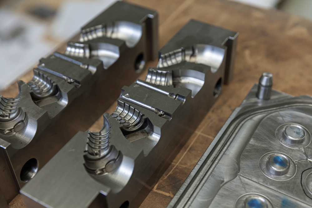
The injection mold consists of the mold core and the mold cavity. A space between the two parts when they come together is the part cavity. This is the void that receives the molten plastic. Single or multi-cavity molds can be created depending on your production needs.
Designing the correct mold for your application is a detailed process requiring high precision and scientific know-how to produce top quality parts with tight dimensions. The proper grade of metal must be chosen for the mold so components that run together do not prematurely wear out. Waterlines must be properly placed to maximize cooling and minimize warping. Engineers must calculate the gate/runner specifications or proper filling and minimal cycle times, and determine the best shut-off methods for tooling durability.
Molten plastic flows through channels called “runners” in the mold cavity. The flow direction is controlled by the “gate” at the end of each channel. The network of runners and gates must be properly designed to ensure even distribution of the plastic during injection and cooling. It is essential to properly place the cooling channels in mold walls to circulate the water essential for the cooling process to result in a product with homogeneous physical properties.
The more complex the injection molded part, the more complex the mold must be. Features such as undercuts or threads typically require more mold components. Other factors that can make a more complex mold are rotating devices, rotational hydraulic motors, hydraulic cylinders, floating plates, and multi-form slides.
Main Stages of Tooling
Manufacturability and Feasibility
In this stage, the client and tooling engineers determine product specifications, mold materials, mold component functionality, operational constraints, and any other product features or enhancements. The mold tooling team examines part geometry and tolerance that could require special tooling features such as slides, lifters, threading or unthreading. The chemical and physical properties of the resin are evaluated so the proper mold can be chosen and mold cooling reviewed. Mold flow is examined to determine the best type of gate and gate locations, as well as proper vent locations.
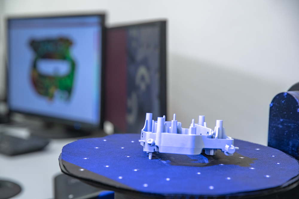
Design
2D and 3D design models are constructed to determine mold and steel sizes. Then the tooling design is finalized.
Final Design Specifications
Any final adjustments or modifications are made, and the tool design specifications are once again reviewed.
Construction of Primary and Secondary Tools
Detailed tool drawings are completed. The tool building process is closely monitored. Then the completed mold is inspected.
Tool Corrections
The tool is examined and any needed adjustments are made. The tool construction is validated, and the process well documented so it can be used again in the future. Parts constructed are examined and scrutinized by the customer. Once final approval is received, the production process begins.
Steel vs Aluminum Tooling
Many molds are made from hardened or pre-hardened steel. It has superior wear resistance. Steel molds are more expensive, but more durable and support a higher rate of production before needing replacement.
Aluminum is also used for tooling. It is easier to machine that steel, so it can reduce building time, and provide faster turnaround and production cycles. Because aluminum is softer than steel, it can be harder to weld and maintain, and can wear more rapidly. It is most suitable for prototypes and short runs. Hybrid molds can sometimes be used that are mostly steel but use aluminum in low-wear areas to transfer heat.
Components of Mold Design
Gates
Gates are openings at the end of the runners that direct the flow of molten plastic going into the mold cavity. They vary in size and shape, depending on the design and material. A number of factors are taken into account to determine the gate types and locations to achieve optimum flow, fill pressure, cooling time, and dimensions.
Draft
The final product must easily be removed from the mold without damage to the surface. This can be accomplished by applying a draft angle or taper to the walls of the mold. There are a number of factors determining the amount or degree of draft angle: part design, materials used, depth of the mold cavity, surface finish, texture, and amount of shrinkage. A few degrees of angle are usually applied to the side walls of the mold creating enough space so the part can easily be removed.
Finish and Texture
Surface finish is determined by mold cooling and part cooling. Molds can be created to apply a texture or pattern to the part surface. Texture can provide a better product function, like reduced wear or an enhanced grip.
Manufacturability and Life Cycle Costs
The purpose of mold design and tooling is to create a product with high manufacturability, that also meets all customer specifications, at the most economical cost.
Correct tooling decisions must be made from the start of the process. Part design and tool design are dependent on each other, so they should be done concurrently when possible.
Tool making can be one of the highest expenses in the production process. By properly designing, building, and using tooling for each part, the engineers of BMI can help reduce costs. Life cycles must be considered. The goal is to have quality and repeatability. These goals can be achieved by using the experienced team of tooling experts at BMI.